
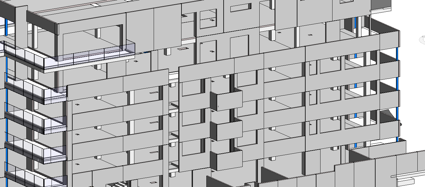
Like most things in Revit, there are many ways to achieve a desired outcome. Take mitered beam joints for example. Modelling precast panels is another prime example of this. A lot of buildings I work on have precast panels, and its my job as a structural draughtsman to model and set-out each panel. Sometimes this is quite straightforward and each panel is fairly rectangular and uniform, but sometimes the panels can be quite complex with lots of voids and steps. This blog post will look to explain the pros and cons of each of the methods we can use to model precast panels in Revit.
Revit Precast Panels using Split with Gap (Disallow joins)
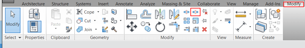
Usually we will model a precast wall as continuous, and as we progress to developed or detailed design we will begin to split the precast wall into individual panels. An easy way to do this is to use the Split with Gap tool. This can be found on the Modify tab. All we do is just specify the Joint gap dimension, then click on the location on the precast wall we want to split.
At wall joins, you can use “Disallow Joins” to separate the panels at corners. Simply right click on the end of the wall (in plan) and select Disallow Join. This stops the walls from wanting to join together.
Pros:
It’s very easy, creates accurate gap dimensions, each panel is a separate wall (useful for tagging individual panels), Vertical and horizontal split,
Cons:
Really only useful for simple panels,
Revit Precast Panels using Reveals
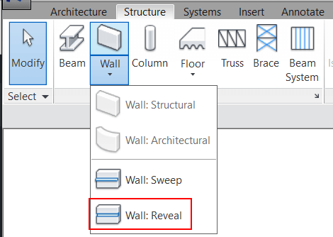
To model precast panels using Reveals, we need to be in a section or elevation view. On the structure tab, click the drop down on the Wall button and select Wall:Reveal.
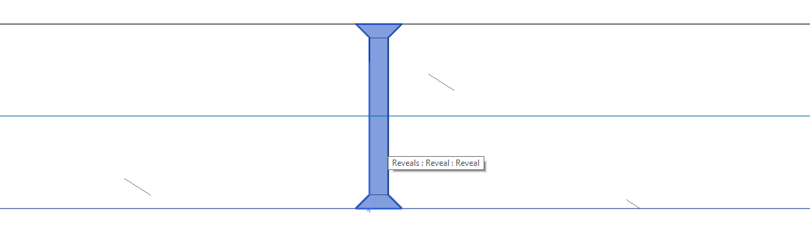
Next choose horizontal or vertical placement, then click on the wall in the location where you want the joint. Select the Wall sweep you just made and edit the type properties. Here you can choose a profile for your panel joints.
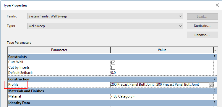
To create this profile, start with the “Profile” family template.
Pros:
Very easy to do, create accurate gap dimensions and profiles, Both vertical and horizontal joints
Cons:
You have to create a profile (extra step), One continuous wall so can’t tag each panel
Revit Precast Panels using Parts
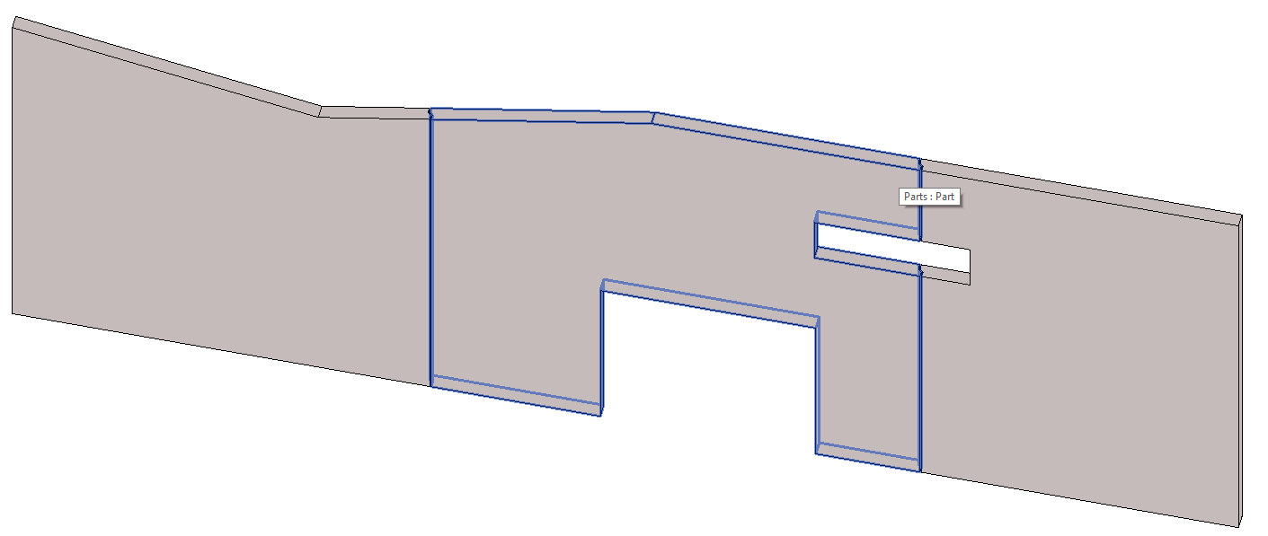
Creating Precast panels using Parts is quite unique, as the Wall remains the same – but in each view you can choose to show the parts(panels) you create or the original wall.
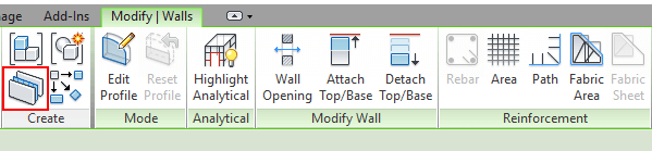
First off, select your Precast wall then click the Parts button under Create on the Modify Walls Tab:
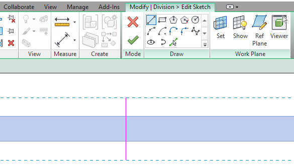
Next, click on Divide Parts then Edit Sketch. Here you can sketch in the location of your panel joints (sketch between the blue dashed lines):
In the properties bar, you have the option to apply a Gap dimension to each joint, and/or apply a profile:
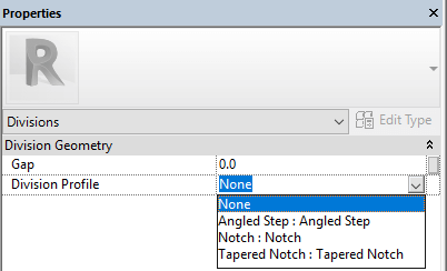
To create this profile family start with the “Division Profile” family template.
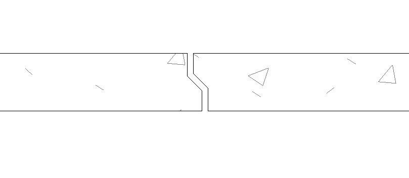
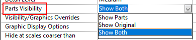
Don’t forget to specify in each view whether you want to show the Parts(panels), show the original Wall, or show both:
Pros:
It’s fairly easy, Creates accurate gap dimensions, Can apply gap profiles, You can tag parts (each panel), Each panel has its own shape handle so can be different thickness etc.
Cons:
Have to specify the Visibility of Parts in each view,
Revit Precast Panels using Curtain walls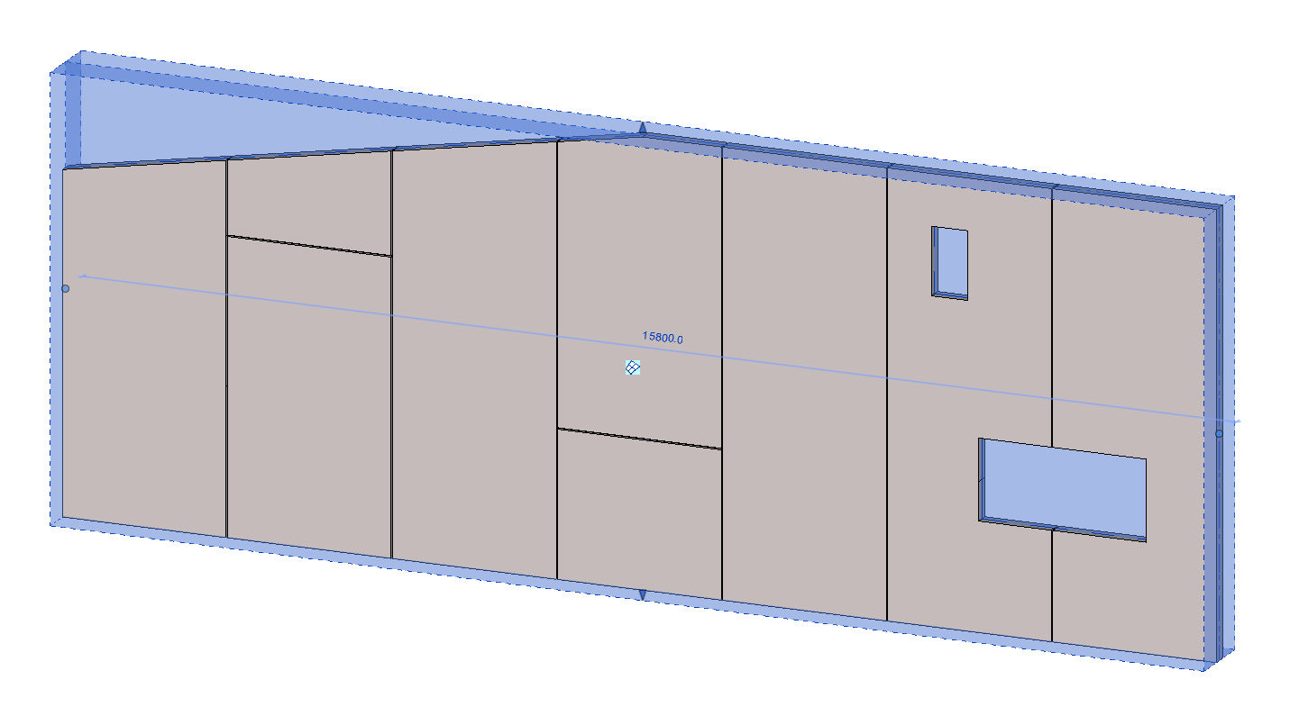
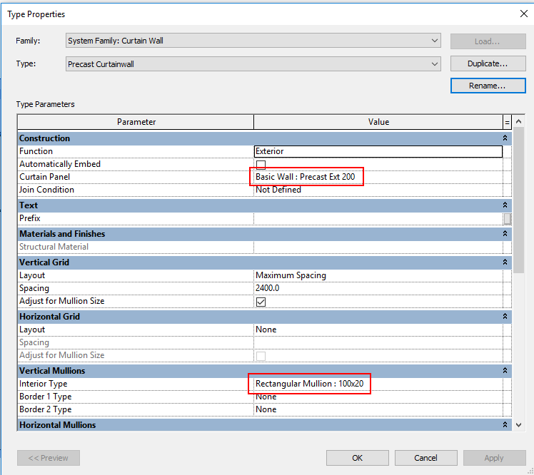
To use this method you need to create a Precast Curtain wall. Set the curtain panel to be a precast wall (or just a concrete wall with the correct thickness).
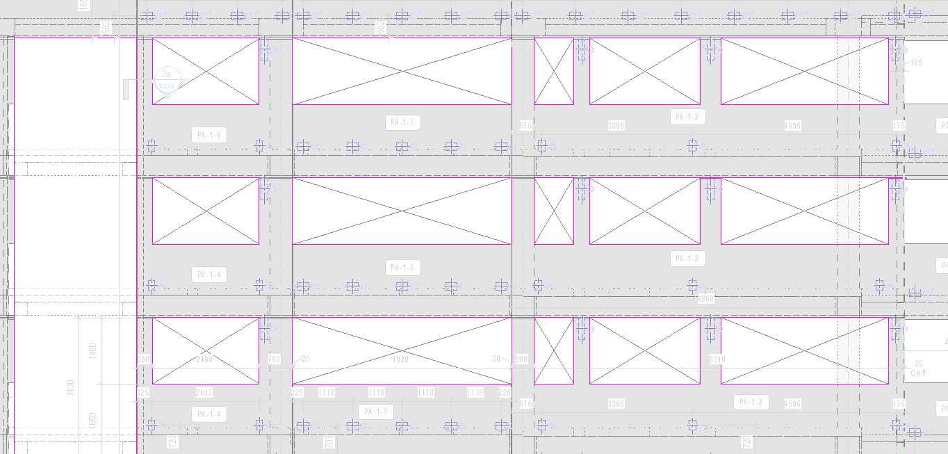
You can then set up the vertical and horizontal grids however you wish. For instance, if you need the panels to be a maximum 2.4m wide you would change the vertical grid layout to “maximum spacing” and the spacing to “2.4m”. Now when you model your wall each panel will be of equal width no greater than 2.4m wide. Alternatively, you can just use the Curtain Grid tool to specify your own Grids.
To make the joints, create a Curtain Wall Mullion with the width being the required gap dimension. Just Hide the Curtain Wall Mullions in your view and you will be left with only the panels with correct gaps. You can use edit profile to create voids or different wall profiles.
Pros:
Fairly easy to set-up, Create accurate gap dimensions, Can set fixed number or maximum width for panels, You can tag individual panels (curtain panel tag), You can use wall openings or edit profile to create voids,
Cons:
Panel gap is actually a Curtain Wall Mullion which you have to hide, You can’t model Reinforcement in Panels
Revit Precast Panels using Voids
I use this method for complex panels. Essentially you have one Precast wall, and create one in-place Void which represents every opening.
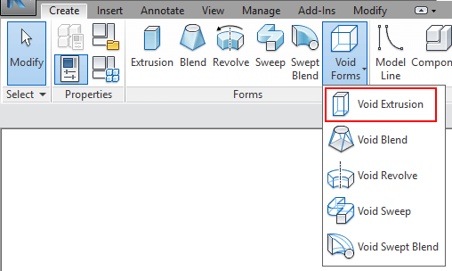
We do this by by creating a ‘Model in-place component’, found on the Structure Tab on the Component drop down:
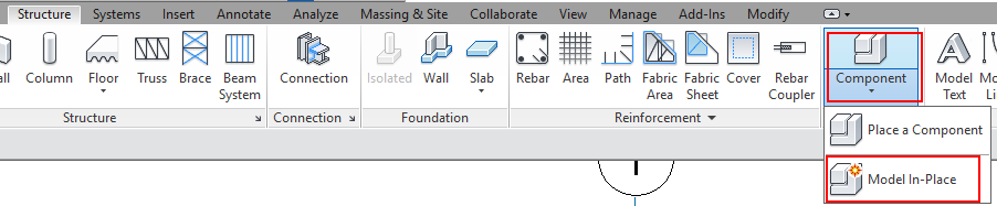
Next select a category (I usually use Generic Model or Wall), and give it a name (I usually call it “Grid (whatever) PC Openings”)
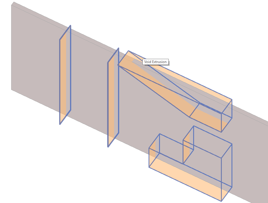
Now we are all set-up, in an Elevation or Section view create a Void extrusion:
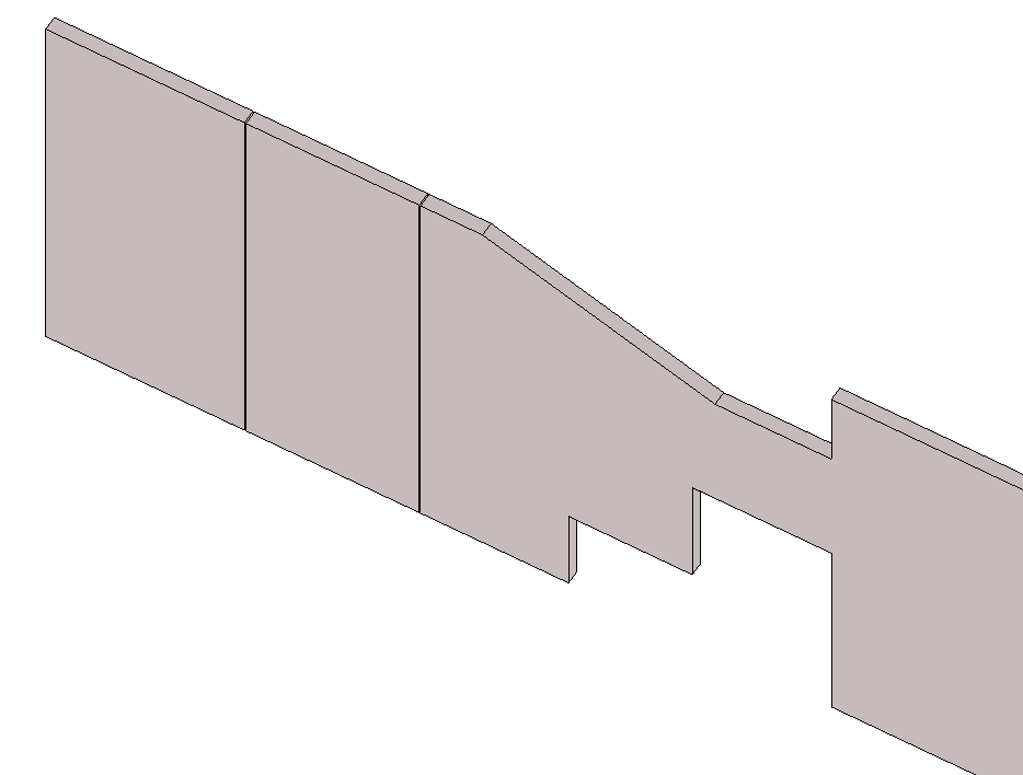
Sketch in all the openings and Panel joints as necessary. Once done hit the big Green tick, then select Cut-Geometry. Make sure the void actually passes through and cuts your wall. Now simply click on the Void you just created, then on the wall you want split:
Hit the big Green Tick and finish the model. All done!
Pros:
Easy to control, You can use sketch tool to create any shaped void, Multiple openings are controlled by one in-place void, good for complex panel systems
Cons:
One continuous wall so can’t tag each panel, can be a pain if one of the panels changes to a different thickness
Revit Precast Panels using Wall openings
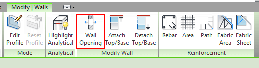
You can use Wall openings to create rectangular voids, either to separate panels (gaps) or to create window and door openings. You do this by selecting your precast wall, then selecting Wall Opening on the Modify Wall tab. This prompts you to create a rectangular opening, which you can edit by pushing and pulling the arrows or editing the temporary dimensions.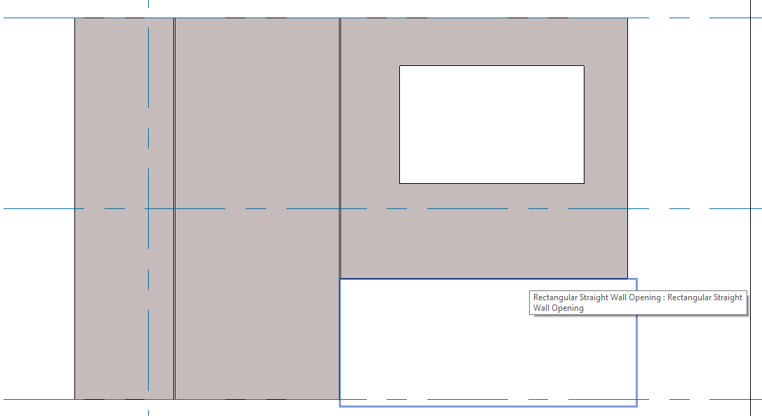
Pros:
Pretty easy, Good for panels with lots of voids
Cons:
Rectangular voids only, can’t use sketch tool, openings are singular so need to group together for multiple.
As you can see there are plenty of ways to model precast panels in Revit, you could even use a combination of these methods to achieve your desired outcome. Hopefully this blog post has given you some new insights or tempted you to try an alternative method for creating Precast Panels in Revit.
If you have any questions, or another method that’s not mentioned then please leave a comment below!
If you found this post helpful, please feel free to share it.
-Talk soon
P.S – I’d love to connect with you on Twitter: here
Join the tribe and Subscribe!
